

Hydrogen Technology Center (HTC)
Charles University in Prague
The Hydrogen Technology Center (HTC) offers testing and analyzing of the users-provided catalysts and cell components for water electrolyzers and fuel cells, ranging from the model half-reaction studies by Rotating Disk Electrode (RDE), through the single cell testing of the complete devices, ending with the evaluation in the whole stacks. The center is located in Prague, Czech Republic.
Half-cell testing
Allows the splitting of complicated processes into individual reactions, which can be investigated separately with high electrochemical precision. In the case of the water electrolyzers, it is Hydrogen Evolution Reaction (HER) and Oxygen Evolution Reaction (OER). In the case of fuel cells, it is Oxygen Reduction Reaction (ORR) and Hydrogen Oxidation Reaction (HOR).
When is this technique useful?
Rotating Disk Electrode (RDE) is an excellent technique for high-precision measurements of the catalyst’s electrochemical properties (kinetics, diffusion constant, etc.). It is useful for high throughput catalyst screening, e.g., a series of bimetallic catalysts with different compositions. On the other hand, it is not a good indication of the actual performance of the catalyst in the real systems, as the reaction conditions are significantly different. The Rotating Ring Disk Electrode (RRDE) can be used for the reduction of the formatted species on the working electrode, which can help to uncover further information about the reaction mechanism.
Offered half-cell setup
The measurements on the half-cell Rotating Disk Electrode, with the complete equipment, several possible experimental configurations, and a fully equipped chemical lab.
Available hardware:
- MSR Rotating Disk Electrode (PINE Research)
- SP-300 bipotentiostat with EIS (BioLogic)
- Accessories (glass, bubbler, all PINE Research)
- Rotating Ring Disk Electrode (Pt ring, PINE Research)
- Heating system for measurements at elevated temperature (heating medium is water)
Available gases:
- O2, H2, N2, Ar, CO
- Special requirements can be satisfied after agreement
Available working electrodes:
- Glassy Carbon, Au, Ag, Ti, Co, Pt
- Special requirements can be fulfilled after agreement
Available reference electrodes:
- Ag/AgCl/KCl, Hg/HgSO4/K2SO4
- Special requirements can be satisfied after agreement
Available counter electrodes:
- Pt wire with ceramic frit
- Special requirements can be satisfied after agreement
Available electrolytes:
- H2SO4, HClO4, KOH, NaOH
- Special requirements can be satisfied after agreement.
Accessories:
- Cleaning sets for electrodes with dedicated slurries and cloths
- pH meter
Water electrolyzer testing in cells
The full water electrolyzer cell allows a real-life simulation of the catalyst’s or cell components’ performance. The single cell consists of a single membrane electrode assembly. Compared to the half-cell, multiple additional effects complicate the actual electrochemical analysis, such as electrical connection, mass transport, membrane degradation, and poisoning by the catalyst. The next step is testing in the whole stacks, which consists of several membrane electrode assemblies and are a further step towards industrialization.
The technical details of the available equipment can be found on the webpage of the Nanomaterials group, which is the home for HTC.
When is this technique useful?
It is the best technique for the catalysts that seem to be promising after the half-cell screening and which are well electrochemically understood. It provides a final confirmation that the catalysts actually work and is an absolutely crucial step to take before any conclusions about the applicability of the catalyst in real electrolyzers.
Offered cell setup
We offer testing of user-provided proton exchange membrane (PEM) or anion exchange membrane (AEM) catalysts in the form of full membrane electrode assemblies (MEA) and catalyst-coated membranes (CCMs). Catalysts in powder form can also be brought and on-site mixed to ink and pressed to the membrane for in-cell measurements. Additionally, various cell components, such as novel AEM/PEM membranes or anode/cathode gas diffusion layers can be compared with commercial parts using referential catalysts.
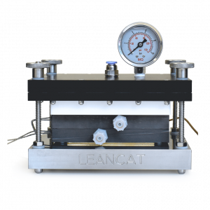
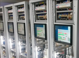
Available cells/stations:
- 2x water fed air pressed single cells with active area of 2×2 cm2, PID controlled heating on the anode and cathode
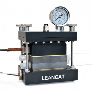
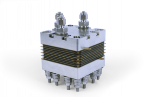
- Water fed, bolt-fastened short stack with active area of 5×5 cm2 per cell
Available potentiostats:
- SP150e potentiostat with EIS (Biologic)
- 2x FlexP0060 booster unit (Biologic), extending the current limits to 50 A (100 A if both units are interconnected) and 60 V
Fuel cell testing
The technique of testing catalysts in a full cell setup is valuable for assessing factors that significantly impact fuel cell operation but cannot be evaluated using the (R)RDE setup alone. Besides characterization of real-world catalyst performance, it provides information on water management, transport of reactants and products, catalyst utilization and durability, membrane properties, and other critical aspects of fuel cell performance. This technique is used for understanding the effects of uneven gas distribution, contact resistance, gas crossover, self-humidification performance, and electrode gas permeability, which are essential for developing durable fuel cells on a large scale.
When is this technique useful?
This technique can be found particularity useful when:
1) one needs to assess real-world performance of catalyst selected by (R)RDE method.
2) optimization of catalyst layer and membrane electrode assembly components for the best performance.
3) estimation of performance of various fuel cell components as membrane, gas diffusion layer, catalyst layer in real conditions.
4) accelerated stress tests of fuel cell components (catalyst layer, membrane)
5) identification of potential/existing problems in fuel cell is needed.
Offered cell setup
We offer fuel cell testing of HOR/ORR catalyst using single-cell, short-stack and full stack setups. Measurements can be performed on acidic or alkaline MEAs prepared by user or using facilities of HTC. Single cell setup can configured for diferent active areas in low-temperature (<80 °C) and high-temperature (up to 200 °C ) configurations. Various components of MEA such as gas diffusion layers, catalyst coated and uncoated membranes, ionomers, etc., can be expensively tested in different gas humidities and cell temperature.
Available equipment:
High temperature cell (up to 200 °C)
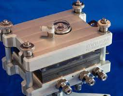
Low temperature (<80 °C) fuel cell short stack
Low/High temperature single cell testing stations
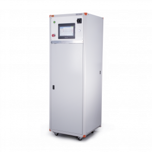
Fuel Cell Poisoning Module (LeanCat)
Available equipment:
- SP150 potentiostat with 10A booster (Biologic)
- PTC0520e potentiostat (Kolibrik.net)
- Electronic loads BK8500b, Maynuo M9711, M9713
Catalysts layer preparation
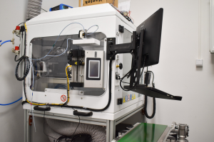
In our HTC lab, we provide an array of advanced techniques to coat catalysts onto substrates like membranes and gas diffusion layers (GDLs). These methods offer precision in controlling catalyst loading, catalyst active area, and distribution. The choice of the most suitable technique depends on several factors, including your unique catalyst properties, the quantity of catalyst required, and the specific characteristics of the membranes, ionomers, and catalyst materials employed.
Our methods include ultrasonic spraying (using the SonoTek Exacta Coat machine), Mayer rod coating, drop-coating, and hot-pressing.
SonoTek Exacta Coat machine
Contacts:
Peter Kúš (tel: +420-95155-2321)
Iva Matolínová (tel:+420-95155-2241)
For more information please refer to the official laboratory website.